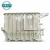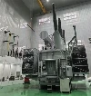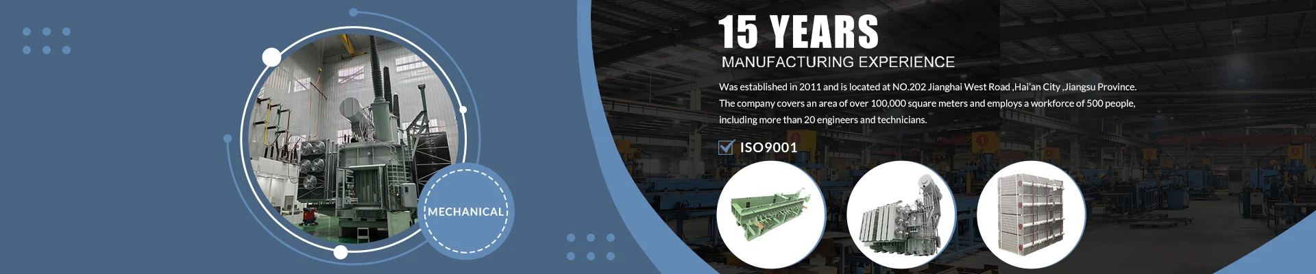

Transformer oil tanks have the potential to cause delays if they are leaking. In a solar step-up substation, rectifying an oil leakage would involve handling the oil, additional testing and possibly rescheduling work around the connection date.
When purchasing, you should make sure the welding processes, dimensional control and inspection reports are considered.
Solar Conditions and Welding for Transformer Tanks
In solar conditions, the output will vary throughout the day. The oil and steel will react to these changes in temperatures. The transformer designer will need to ensure that there is consideration for the temperature range, oil expansion and pressure.
Ensure that for the sealed tank transformer, there is consideration for oil expansion. Main transformers with conservators will have a different design, so don't copy the requirements from a hermetically sealed distribution unit.
Provide the fabricator with information on working temperatures, any vacuum requirements and transportation requirements. There is no reason for increasing the weld size for solar applications. The welds need to be appropriate for the design.
If the solar site is in a coastal environment, there should be consideration for corrosion at the weld toe. If the site is remote, it may cause issues for repairing in the field. This should be noted in the procurement.
Potential for Leaks and Structural Issues with Poor Welds
The oil tank plays an important role in the design of the transformer. The welds in the tank need to be able to withstand the pressure, handling and loading requirements.
A simple calculation illustrates the force involved:
Force = Pressure Difference × Area
With a pressure difference of 20 kPa over a 1 m² panel, there will be a 20,000 N-or 20 kN-force applied.
This is only a calculation example, not a recommended operating or test pressure.
Check that the seams, base-to-wall joints, nozzles and fixings are correctly welded. Pores or cracks in the welded joints can cause leaks. Poor fixings can also cause concern for structural issues.
Ensure that there are fixings specified for the empty tank. If there are any fixings approved for the assembled transformer, specify which ones.
Material Selection and Joint Preparation
Ensure that the steel grades and thicknesses are specified for the tank walls, base, lid, flanges and reinforcement. The welding procedure should be appropriate for the material and joint.
Porosity can occur due to gas bubbles getting trapped in the weld. These can occur due to moisture, oil or grease, and lack of shielding (TWI).
Ensuring that the joint edges are clean and the consumables are stored correctly will have a direct effect on the weld finish.
Joint preparation should be checked prior to welding. Ensure that:
The joint edges are aligned.
The root gaps are correct.
The preparation angle is correct.
There is sufficient access.
Don't overweld. Material substitutions should be recorded and approved prior to cutting any replacement material.

Welding Procedure and Welder Qualifications
A Welding Procedure Specification (WPS) should be provided to show what welding has been done for the joint. Request the relevant procedures, evidence of the welder/operator qualifications and any supporting evidence for the welder qualifications.
Although robotic welding can be repeated, the weld will depend on the joint being in the correct position, clean, equipment in good condition and parameters controlled. Manual joints and repair welds also need to be considered.
Welding is a specialist process, and there needs to be control over the people involved, welding procedure, inspection and traceability (TWI).
Having a generic quality certificate won't prove that a specific joint was welded correctly. (TWI)
Ask how variations are recorded.
If there are lots of repeated seams, check the first tank completed. Check that the setup is as per the qualified procedure. If there are variations in plate thickness or joint position, this should be reviewed.
Controlling Distortion on Flanges and Equipment Fixings
As the weld metal and surrounding steel cool down, they will contract. This can cause movement in radiator fixings, distortion in the lid flanges and changes in mounting dimensions on large power transformers.
Flanges can distort, causing uneven compression of the gaskets. This can cause issues for installers trying to get a good seal, even though they have used the correct gasket and bolts.
Distortion can be controlled by weld size, weld order, balanced welding and correct fixturing (TWI, Controlling Distortion by Fabrication).
Agree that dimensional checks will be carried out after welding. Check that the flanges are flat and that centre points and mounting points are within the drawing tolerances.
Try to fit the lids and radiators to check for any assembly issues.
Non-destructive Testing and Visual Checks
Visual checks can only be carried out on accessible areas. To check that the welds are sound internally, nondestructive testing (NDT) should be carried out. Choose the NDT based on the joint type, thickness, accessibility and defects being investigated.
Large main tanks can be leak tested using an approved air-pressure test with leak-detection solution (TWI).
Leak testing should be carried out prior to painting. Further checks should be outlined in the inspection plan.
IEC 60076-1 contains requirements for vacuum, pressure and leak testing. Check the contract to confirm which requirements are needed.
Agree on the following:
Test pressure.
Gauge or absolute pressure reference.
Holding time.
Test medium.
Inspection coverage.
Passing the leak test doesn't prove sufficient structural strength or vacuum capability.

Repairing, Retesting and Surface Preparation
If the inspector finds any defects, the repair should address the cause of the defect and restore the joint. Remove any unacceptable material and reweld the joint using an approved procedure. All required testing should be carried out.
Record the repair, showing where it was repaired, what was done and that it was accepted.
If defects are found regularly in similar joints, this should be reviewed. Consider changing the preparation, equipment or parameters.
Once the weld has been accepted, it should be cleaned. Remove any weld spatter, inspection residues and internal debris.
Internal debris, such as loose grinding and welding material, could enter the insulating oil. Ensure that the openings are kept clean during storage and transportation. Specify who will check cleanliness prior to assembly.
If there is a need for oil removal on site, there may be a separate storage tank for the transformer oil. This needs to be clean and compatible with the oil. Testing of the oil will determine whether it can be reused.
Information to Request Regarding Welding and Acceptance
A useful inspection package should be provided to show what welding has been done on each tank. This should include:
Approved drawings.
Material identification.
Welding procedures.
Test results.
Repair records.
Acceptance records.
The documents should clearly state what has been supplied. Ensure that the welds behind the reinforcement and around fixings can be accessed.
If you have a batch of 10 tanks and 100% leak testing is required, you should request results that can be traced back to all 10.
100% means that all tanks have been tested; it does not mean there is no possibility of future failures.
Ensure that witness points, reporting requirements and responsibility for retesting are defined. Use the same inspection criteria to compare quotations.
Prior to ordering, ask the chosen supplier to provide a welding inspection plan based on your approved drawings. Agree on any exceptions and attach the acceptance criteria to your contract.