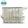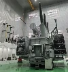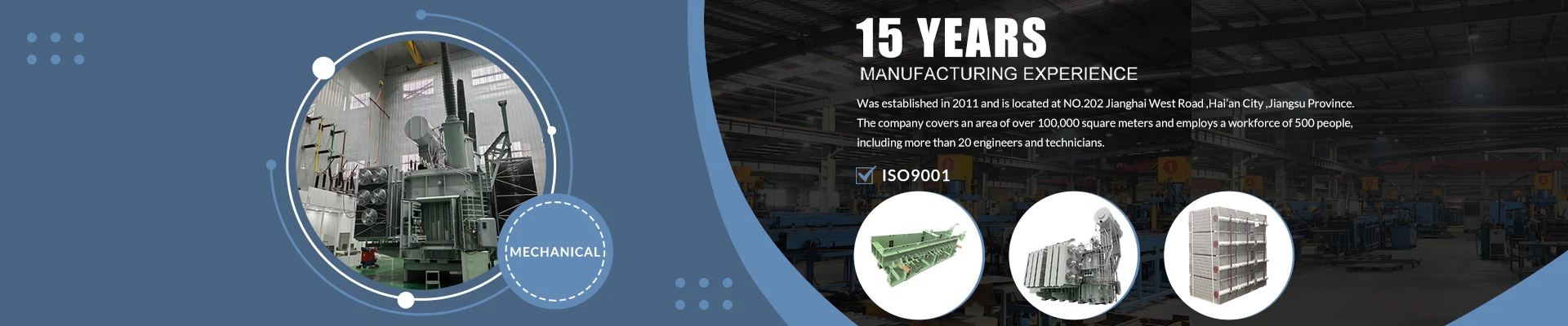
A transformer oil tank may pass leak testing yet have incorrect radiator connections. Correcting these interfaces at the substation can result in extra work and downtime. Oil may need to be drained, coatings repaired, and leak tests repeated.
Start with an approved design and interface drawing. Then compare fabrication, testing, transport, and prices against the same requirements.
Transformer Rating & Tank Design Parameters
- Provide the fabricator with the following information:
- Transformer rating and equipment layout.
- Type and volume of insulating fluid.
- Operating temperature range.
- Installation and site conditions.
Voltage and MVA alone are not enough to define the tank design.
Confirm the oil preservation arrangement. A conservator system and a hermetically sealed design handle oil expansion differently. The transformer designer should specify operating pressures, vacuum requirements, and the cooling arrangement.
Provide transformer losses and cooling interface requirements. The tank and cooling equipment must work together within the complete thermal design. Adding steel does not establish sufficient cooling capacity.
Clarify the supply scope: are the cover, conservator, radiators, valves, gaskets, and accessories included, or is the supplier providing only their mounting interfaces?
Tank Size & Interfaces
Check that the internal dimensions accommodate the core-and-coil assembly, insulation clearances, bracing, and lead wiring.
Review the external arrangement for:
Bushings and tap changer interfaces.
Radiator flanges.
Drain valves.
Monitoring connections.
Both the fabricator and equipment integrator should use the same drawing reference points. Specify tolerances for flange centre distances, bolt patterns, and mounting points.
For replacement projects, check the existing foundation and clearance around rails, cables, and surrounding equipment. Old drawings may not show previous alterations.
Allow enough space to operate valves, open inspection covers, and replace radiators. A tank that fits the foundation may still restrict maintenance access.
 Material Grade & Plate Thickness
Specify the steel grade and plate thickness for each part of the transformer oil tank, including the walls, base, cover, flanges, and stiffeners. These components carry different loads.
For a simple illustration:
Force = Pressure difference × Area
30 kPa × 2 m² = 60 kN
This example shows the resultant force acting over a flat panel. It is not a recommended operating or test pressure. The panel's response depends on plate thickness, stiffener spacing, support conditions, and the overall structural arrangement.
Vacuum conditions also require structural review. External pressure during vacuum processing can cause buckling.
Any design changes should be approved. Increasing plate thickness alone may not resolve an unsuitable steel grade or stiffener arrangement.
Weld Quality, Flange Seals & Internal Cleanliness
Ask the fabricator to confirm:
Welding procedures and required welder qualifications.
Inspection of seams, corners, nozzles, and load-bearing attachments.
Inspection of welds before stiffeners or other components make them inaccessible.
Repair procedures and subsequent inspection.
Welding can distort flange faces and mounting points. TWI describes measures such as suitable welding sequences, balanced welding, and controlled assembly practices to reduce distortion. Take critical measurements after welding. TWI
For bolted covers, check flange flatness, gasket material, bolt patterns, and tightening requirements. Gaskets must be compatible with the insulating fluid and operating temperature.
Remove welding debris, grinding residues, and inspection materials from the transformer tank. Protect openings during storage and transport. A clean exterior does not establish internal cleanliness.
 Corrosion Protection
Identify the installation environment before selecting a coating system. Consider coastal salt, industrial pollution, humidity, ultraviolet exposure, and standing water.
Agree on:
Surface preparation.
Coating products and application sequence.
Dry film thickness.
Curing requirements.
Repair procedures.
Environmental corrosivity and coating durability are separate specification items. Under ISO 12944, the high durability category covers 15–25 years to first major maintenance. This is a maintenance planning range, not a warranty. ISO 12944 coating guide
Ensure access for coating around stiffeners, welds, lifting attachments, and the base. Request recorded coating thickness measurements.
Any internal coating should be approved for compatibility with the selected insulating fluid.
Pressure, Vacuum & Leak Testing
IEC 60076-1 includes requirements concerning pressure, vacuum, and leak testing. Identify the contractual requirements and agree on the applicable procedures. IEC 60076-1
For each test, define:
Pressure or vacuum level.
Gauge or absolute pressure reference.
Test medium and setup.
Holding time.
Covers, valves, and cavities included.
Acceptance criteria.
An approved air-pressure test with leak-detection fluid can identify leakage at accessible joints. Carry out the agreed weld leak testing before coating, and specify any subsequent testing in the inspection plan.
Repairs require inspection and retesting.
Passing a leak test does not establish vacuum capability or acceptable deformation. These are separate requirements, and results should be traceable to each transformer tank.
Lifting & Transport Requirements
Confirm the intended duty of each lifting attachment. Is it designed for the empty power transformer oil tank, the active part, or the assembled transformer?
Review:
Transport weight and centre of gravity.
Shipping dimensions and restraint points.
Access into the substation.
Accessories removed for shipment.
Responsibility for reinstalling those accessories.
Protect machined flange faces and cap openings. Apply transport restraints only through approved structural points.
Coordinate with the installation contractor on unloading, jacking or rolling, crane lifting, and placement onto the foundation. The transport arrangement must suit the site's access and handling constraints.
 Cost per Kilogram & Delivery
Compare quotations for the power transformer oil tank using the same approved drawing revision. Establish the billable weight basis: bare fabricated steel, the finished assembly, or another agreed definition.
The figures below are illustrative and are not market quotations.
| Cost Item | Supplier A | Supplier B |
|---|---|---|
| Agreed billable weight | 6,000 kg | 6,000 kg |
| Unit price | USD 2.60/kg | USD 2.80/kg |
| Base amount | USD 15,600 | USD 16,800 |
| Required coating upgrade | USD 1,500 | Included |
| Required packaging | USD 500 | Included |
| Comparable subtotal | USD 17,600 | USD 16,800 |
Freight and taxes are excluded. Although Supplier B has a higher price per kilogram, its comparable subtotal is USD 800 lower once the required coating and packaging are included.
Confirm what triggers the start of manufacturing. Allow time for inspection, coating curing, packaging, and transport. Distinguish factory completion from arrival at the substation.
Send shortlisted suppliers the same technical package and request a priced deviation list. Attach the agreed drawings, supply scope, inspection plan, weight basis, and delivery schedule to the purchase order.