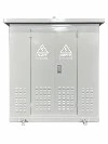
A substation alongside an apartment block requires openings to exhaust heat from components and enclosures, but they must present minimal risk to people.
Residential substation enclosures need an airflow strategy that balances their rain protection: baffle designs, drainage, and sealing measures will all interact with the cooling performance of the installation.
1. Assesses Transformer Heat Losses and the Weather Conditions
Using the predicted losses from the transformer, at the chosen loading, and adding in other losses and solar effects, establish the heat removal requirements: just specifying the capacity in kVA will not suffice.
An example heat balance calculation shows the level of airflow needed to achieve the desired cooling:
Assuming 10 kW of heat to be exhausted by the ventilation on a 10 K rise in temperature, the airflow would be:
Airflow (m³/h) = 3600 × heat load (W) / [air density (kg/m³) × specific heat (J/kg·K) × temp rise (K)],
So 3600 × 10000 / (1.2 × 1005 × 10) ≈ 3 000 m³/h.
That calculation assumes that buoyancy and other losses will contribute sufficiently and that the ambient temperature rise at the intake is acceptable. If the ambient temperature is already higher than the permissible operating value, larger openings will not help.
Establish your specific site conditions that apply to equipment sizing, such as prevailing temperatures and humidity, and altitude, and risk of exposure to storms or extremes of weather. A sheltered court on the inside of a building will be very different from an exposed location on the coast.
2. Positions Air Inlets and Outlets to Enable Natural Ventilation
Place low-level intakes and upper-level outlets to let warmed air to rise and escape around the transformer compartment; Schneider Electric recommends that, if possible, openings of ventilation should be provided in the upper and lower parts of the enclosure in the vicinity of the transformer, but not close to switchboards to the extent possible by the location of installed equipment.
Ensure that the complete circuit of airflow, as installed, is unobstructed by any supporting structures or cables trays, partitions, and acoustic screens.
On the outside, maintain clearances required by the manufacturer of the electrical installation from walls or fences and plants: landscaping to the outside of an enclosure takes time to grow, so confirm if the anticipated opening will remain available once vegetation has matured.
The size and position of the ventilation openings should be consistent with the design of an electrical installation, and modification to partitioning and baffles for airflow control must retain required clearances for electrical equipment and pressure relief openings.
3. Selects Louvers that Balance Airflow and Rain Resistance
Specify louvers based on the expected resistance to airflow and penetration by rain at the designed airflow rate: visual appearance of blades gives no indication of either.
AMCA 500-L includes test data for both performance in airflow and resistance to rain penetration. Published performance data on louvers includes tests for wind-driven rain at 75 mm/h rainfall and 13 ms/s wind speed, and gives the corresponding performance of the louver at varying rates of ventilation air movement: those are test conditions for one set of conditions.
Confirm the free area of the louver: a 1.0 m² panel with 50 % free area gives 0.5 m² of effective opening. Operating at 3000 m³/h gives a free area velocity of 1.67 ms/s.
The operating point for the louver (in this context, pressure drop) is shown by its pressure-drop curve, which is compared with rain penetration test data.
4. Includes Roof Overhangs and Rain Hoods to Shield Ventilation Openings
A roof overhang protects the upper ventilation openings from the direct action of rainfall; drip edges to discharge the runoff from the roof further away from the panel face or a suitably-sized hood.
The hood must leave adequate space for the hot air to be exhausted, and a narrow clearance behind a large cover can restrict air movement and induce recirculation of hot air.
Design the roof edge, hood, and louver as a single assembly, and consider the direction of the anticipated runoff, the likely direction of storm winds, exposure of corners, and access for cleaning.
Wind can drive rain horizontally underneath a roof overhang, so the sheltered opening still requires adequate rain resistance; confirm that the deflection of the roof under the specified loading will not turn a gentle slope into a ponding situation.

5. Considers Airflow Resistance from Mesh Screens and Filters
Fine mesh may restrict the passage of insects, depending on the aperture size, but additional pressure drop and a workable cleaning regime is necessary for finer material. Natural ventilation lacks pressure to overcome resistance.
Assemble a complete assessment of resistance to airflow through the entire aperture assembly, louvers, mesh, filters, and internal baffles: confirm that the data provided apply to the chosen screen or filter media.
For a site adjacent to trees or sources of airborne dust or pollen, establish access arrangements appropriate to the expected accumulation on screens or louvers: a filter that cannot be conveniently cleaned will impede the airflow.
When fans become appropriate, consider their noise at the nearest residence, maintenance and accessibility, and consequences of failure.
6. Seals Doors, Junctions and Cable Entries
Airflow should only take place at specified openings: gaps around doors and joints and improperly sealed penetration for cables provide uncontrolled entry of water or humid air.
Ensure the continuity of a gasket at corners and the compression around hinges and the spacing of latches: large doors in sheet metal require adequate stiffness to retain a continuous seal across the door face.
Roof joints and fixing points also require examination after installation: sealant over the joints may mask intermittent failures of a junction or fixings.
Select glands on or through which cables will pass, and secure any unused entry to the enclosure.
The junction with the foundation and cable trench should also offer resistance to entrance of moisture: water can wick up the back of sealed panels, particularly at places where the panel is smaller than the size of the foundation.
7. Designs Drainage to Prevent Water Accumulation
Water admitted to the louver should have a continuous route back to the exterior: sloped openings, drains, and drip details can prevent such water accumulating in the enclosure.
Ensure continuity of drainage and consider the finish applied to the enclosure: paint buildup, sealant, and installation debris can block the narrow passages of drainage devices.
Drain outlets must comply with the declared ingress and contact protection: separate normal rainwater drainage from any containment system for transformer fluids.
Examine the ground around the enclosure: water run-off and irrigation should be directed well clear of the foundation. Where flooding is likely, that is a separate subject: measures to resist flooding are not the same as protection from rain.
Condensation can accumulate on the surface of cold parts of the enclosure even with intact rain seals, and particularly in conditions of high humidity and varying loads.

8. Confirms Ventilation Performance and Rain Protection in the Complete Enclosure
The combination of all the doors, louvers, screens and hoods, internal partitions, and all entries for cables in a completed enclosure must be checked for performance: a component tested in isolation cannot represent the whole installation.
Confirm the particular IEC 60529 test conditions and requirements applicable to the installation: IPX4 protects against the direct action of water from any direction, but it may be pertinent to test against wind-driven rainfall for an exposed site.
If there is an applicable prefabricated substation, IEC 62271-202:2022 includes an annex of test conditions and general requirements applicable to assembly. Confirm the cooling performance with representative equipment, load, and installation conditions.
Before a purchase is made, arrive at an agreement on the heat loss figures, the details of the enclosure ventilation, and drainage, and documents on which tests will be performed for acceptance: this ensures there is a reference that can be applied to both the enclosure manufacturer and equipment integrator.
Discuss Your Substation Enclosure Requirements
ZHIHE manufactures custom sheet-metal substation enclosures to approved drawings. Send us your enclosure layout, installation location, material and coating requirements, and order quantity. Include the specified ventilation and ingress-protection requirements so we can review the fabrication details and prepare a quotation for your project.
FAQ
Q: How soon can you delivery the transformer?
A: It depends on the quantity and drawings, normally within 15 days since the date drawing confirmed by buyer
Q: What payment method do you accept?
A: T/T (wire transfer)